How to Load PCB Assemblies in a Multi-Layer Drying Oven for Consistent Drying
PCB Drying Process Guide
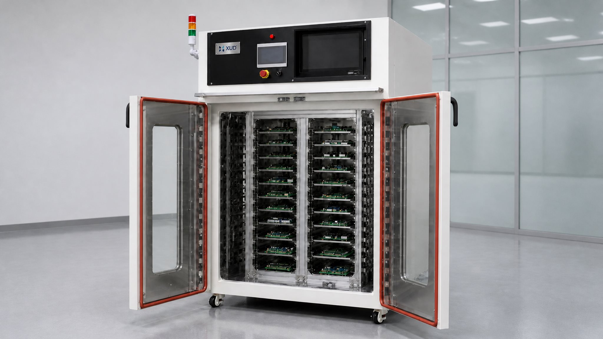
How to Load PCB Assemblies in a Multi-Layer Drying Oven for Consistent Drying
A practical guide to tray arrangement, board spacing, loading density, airflow access, and process validation for electronics manufacturers.
Loading PCB assemblies into a multi-layer drying oven may seem straightforward: place the boards on trays, slide the trays into the chamber, and start the drying cycle. However, the actual loading arrangement can have a significant influence on how consistently heat reaches the products.
A drying oven may have a suitable temperature range and a forced hot air circulation system, but these features alone do not guarantee consistent results under every loading condition. Closely spaced boards, blocked air passages, oversized trays, and uneven loading can change the way heated air moves through the chamber.
This guide explains how to arrange PCB assemblies in a multi-layer drying oven, how to evaluate tray spacing and loading density, and how to verify whether a loading configuration is suitable for actual production.
Table of Contents
- Why PCB Oven Loading Matters
- How to Arrange PCB Assemblies on Trays
- How Much Space Should Be Left Between Trays?
- How to Determine the Right Loading Density
- How to Load Different PCB Sizes and Product Types
- How to Maintain Airflow Through a Multi-Layer Rack
- How to Validate a PCB Oven Loading Arrangement
- Common PCB Oven Loading Mistakes
- When Should You Use Custom PCB Drying Racks?
- Frequently Asked Questions
1. Why PCB Oven Loading Matters
The usable capacity of a drying oven is not determined only by its internal dimensions or the number of available trays. The arrangement of the products inside the chamber affects how heated air reaches the load and how consistently the process can be repeated.
1.1 Loading Density Can Change Airflow Conditions
When too many PCB assemblies are placed close together, the open spaces between products become smaller. Depending on the airflow design, this may increase resistance in some passages and cause air to bypass other areas.
For example, a rack with ten trays does not necessarily perform better when every tray is filled to its maximum physical capacity. If the products cover important airflow paths, some positions may receive less effective air movement than others.
1.2 Product Arrangement Affects Heat Exposure
PCB assemblies contain different materials, component heights, connectors, housings, and other features. These differences can influence how heat reaches individual areas of the assembly.
Two boards placed in different positions may experience different heating conditions, particularly when one is exposed to moving air while another is shielded by a tray edge, neighboring board, or large component structure.
1.3 Repeatable Loading Is Important for Batch Production
One often-overlooked issue is the difference between the loading arrangement used during process development and the arrangement used by operators during daily production.
If operators change the number of boards per tray, tray positions, or product orientation from one batch to another, the thermal conditions may also change.
For this reason, a production loading specification should define not only the drying temperature and holding time, but also the tray configuration, product orientation, and maximum approved loading quantity.
A useful production question is not simply, "How many PCBs can fit inside the oven?" It is, "How many PCBs can be processed under a loading arrangement that has been verified and can be repeated by different operators?"
2. How to Arrange PCB Assemblies on Trays
The correct tray arrangement depends on the PCB dimensions, assembly structure, component height, handling requirements, and drying objective. The tray should support the product securely without unnecessarily covering the surfaces that need exposure to circulating air.

2.1 Avoid Direct Board-to-Board Contact
PCB assemblies should not be placed in direct contact with one another unless the product design and an approved fixture specifically allow it.
Uncontrolled contact can create several problems:
- Components may touch neighboring boards or tray surfaces.
- Air movement around contact areas may be restricted.
- Connectors, soldered components, and delicate structures may be damaged during handling.
- Products may shift when trays are inserted or removed.
Where multiple assemblies are placed on one tray, their positions should be clearly defined. Dividers, slots, locating features, or dedicated holders can help maintain consistent spacing.
2.2 Horizontal Loading: When Is It Suitable?
Horizontal loading places the PCB assembly flat on a supporting tray or fixture. This arrangement can be practical when the assembly has a stable support surface and the tray can accommodate its dimensions and weight.
However, the supporting surface should be evaluated carefully. A large solid tray underneath the board may reduce airflow access to the lower surface. The effect depends on the tray construction, openings, board geometry, and oven airflow direction.
For assemblies with components projecting from both sides, the fixture must also prevent components from carrying the product's weight or contacting the tray.
2.3 Vertical or Slotted Loading: When Is It Suitable?
Vertical loading uses slots or holders to keep individual boards upright. It may help reduce the footprint occupied by each board and provide access to both sides, depending on the rack design.
This arrangement is not automatically better for every PCB assembly. Boards must be sufficiently supported, and their components must not collide with adjacent products. Heavy assemblies or products with uneven weight distribution may require additional mechanical support.
Before adopting vertical loading, check:
- Whether the PCB can remain stable in the holder.
- Whether components are protected from mechanical contact.
- Whether the holder blocks important airflow areas.
- Whether operators can load and unload boards safely and consistently.
2.4 Protect Components and Sensitive Areas
PCB assemblies are not flat, uniform products. Tall capacitors, connectors, plastic housings, heat-sensitive parts, and other components can create different support and airflow requirements.
Tray contact points should be selected based on the mechanical strength of the assembly. Avoid placing the full product weight on fragile components, solder joints, or connectors.
For products with different heights or irregular shapes, a custom fixture may be more suitable than a general-purpose flat tray.
3. How Much Space Should Be Left Between Trays?
There is no single tray spacing measurement that applies to all PCB drying ovens. The required clearance depends on the chamber dimensions, supply and return air locations, rack design, product size, and the amount of space occupied by each loaded tray.
Instead of selecting a distance based on guesswork, manufacturers should evaluate the available airflow passages in the actual loaded configuration.
3.1 Consider the Complete Loaded Tray Height
When calculating vertical clearance, consider the entire loaded assembly rather than the tray alone.
The effective height includes:
- The tray or support frame.
- The height of the PCB itself.
- The tallest components mounted on the PCB.
- Any holder, divider, or locating fixture.
A tray may appear to have sufficient clearance when empty, but the components installed on the PCB can significantly reduce the remaining open space.
3.2 Check the Space Between the Product and Tray Above
The distance between trays should be evaluated together with the height and orientation of the loaded products.
For example, if tall components are positioned directly below the next tray, the available passage for circulating air may be restricted. A tray arrangement that looks spacious when viewed from the front may have narrow passages around the actual components.
3.3 Consider Side Clearance and Chamber Walls
Clearance is also needed around the sides of the rack and between the loaded products and chamber walls. Products placed too close to air supply or return openings may interfere with the intended circulation pattern.
The correct clearance is determined by the oven's airflow design, not by a universal distance. It should be checked using the actual rack, trays, and representative products.
When requesting a custom multi-layer PCB drying oven, provide the maximum loaded tray height, tray dimensions, product dimensions, and the number of required loading levels. These details are more useful for rack design than providing only the number of PCBs per batch.
4. How to Determine the Right Loading Density
Loading density describes how much product is placed in a given chamber or rack space. It is one of the most important factors to consider when balancing batch capacity and drying consistency.
Increasing the number of boards per batch may improve nominal output, but it can also change the airflow resistance, product exposure, and total thermal load.
4.1 Calculate Capacity from the Real Product Arrangement
Start by determining how many products can be positioned safely on each tray. Then calculate the total quantity based on the number of usable tray levels.
For example, a preliminary capacity estimate can be expressed as:
PRELIMINARY LOADING CAPACITY
Total Batch Quantity = Boards per Tray × Number of Loaded Trays
This is only a physical capacity calculation. It does not prove that the resulting loading density is suitable for the drying process.
The approved production quantity should be established after checking airflow access, mechanical support, temperature response, and the actual process result.
4.2 Avoid Filling Every Available Space
A common mistake is treating every open area inside a tray or chamber as usable product space.
In practice, some areas must remain available for:
- Air circulation around the products.
- Access to product surfaces that require drying.
- Mechanical support and safe handling.
- Clearance around rack frames and chamber air passages.
A lower but validated batch quantity can be more valuable than a higher nominal capacity that produces inconsistent results or requires frequent reprocessing.
4.3 Record the Approved Loading Pattern
Once a suitable arrangement has been established, document it as part of the production procedure.
A practical loading record may include:
- Product model or PCB assembly identification.
- Tray or fixture identification.
- Number of products per tray.
- Number of trays used per batch.
- Product orientation and designated tray positions.
- Approved drying recipe and batch identification.
Photographs or simple loading diagrams can help operators reproduce the same arrangement across different shifts.
5. How to Load Different PCB Sizes and Product Types
Electronics manufacturers may process different PCB dimensions or assembly models using the same drying equipment. This creates an additional challenge: a tray arrangement suitable for one product may not be appropriate for another.
5.1 Small PCB Assemblies
Small boards can often be arranged in multiple positions on one tray. However, small dimensions do not automatically mean that more boards can be loaded without restrictions.
Use locating features or dividers where necessary to prevent products from shifting. Ensure that the boards remain separated and that the arrangement does not create densely packed groups that obstruct airflow.
5.2 Large PCB Assemblies
Larger assemblies may require individual tray positions or wider supporting frames. Pay particular attention to the distance between product edges, tray supports, and chamber walls.
Large boards can also have uneven component layouts. The support structure should be designed around the actual product geometry rather than assuming that the board is a completely flat surface.
5.3 Mixed-Size Loading
Loading different PCB sizes in the same batch may be possible when their process requirements and handling arrangements are compatible.
However, mixed-size loading needs additional evaluation because:
- Large boards may shield smaller products from moving air.
- Different product heights can change the open airflow passages.
- Different materials and component structures may respond differently to heat.
- Different process requirements may make a shared drying recipe unsuitable.
For products with substantially different thermal requirements, separate batches or product-specific recipes may be more appropriate.
5.4 Bare PCBs and Assembled PCBAs Are Not the Same Load
This distinction is particularly important.
Bare PCB drying is often associated with reducing moisture absorbed by laminate materials before subsequent manufacturing operations. Assembled PCB drying after cleaning has a different objective: removing remaining moisture or cleaning residues while protecting mounted components and other sensitive materials.
The two processes should not automatically share the same temperature, holding time, tray arrangement, or loading density.
For assembled boards, check component temperature limits, connector materials, adhesives, plastics, coatings, and the cleaning agent used. The process should follow the product manufacturer's requirements and be verified using representative assemblies.
Read more: How to Dry PCB Assemblies After Cleaning Without Exposing Components to Excessive Heat
6. How to Maintain Airflow Through a Multi-Layer Rack
Forced hot air circulation helps distribute heat throughout a drying chamber. However, the effectiveness of the circulation system depends partly on whether the loaded products and trays allow air to move through the intended passages.
It is useful to distinguish between two functions:
- Air circulation: moves heated air through the chamber and around the products.
- Exhaust ventilation: removes a portion of the chamber air, including moisture or vapors, according to the equipment design.
These functions are related but not interchangeable. A circulation fan does not automatically provide sufficient moisture removal, and an exhaust opening does not guarantee that air reaches every product surface.
6.1 Do Not Block Supply and Return Air Openings
Before finalizing a tray arrangement, identify where heated air enters the chamber and where it returns to the circulation system.
Large trays, rack frames, or closely positioned products should not obstruct these important passages. The actual effect depends on the oven's internal duct and circulation design.
6.2 Watch for Airflow Bypass
Air may follow the path of least resistance. If the rack arrangement creates a large open channel on one side but restricts the product area, a portion of the circulating air may bypass the load.
This is why a visually balanced rack does not necessarily guarantee balanced airflow around the products.
When evaluating a loading arrangement, check the areas closest to the air supply, the center of the rack, and the areas near the return air openings.
6.3 Consider the Effect of Tray Construction
Tray material, thickness, openings, frame structure, and edge design can all influence the usable airflow area.
A solid tray may be suitable for some products but can restrict airflow to surfaces underneath it. A perforated or open-frame design may provide more air access, provided that it can safely support the PCB assembly.
The best tray is therefore not necessarily the one with the most openings. It is the one that provides appropriate mechanical support while fitting the oven's circulation design and the product's handling requirements.
6.4 Do Not Assume That Increasing Fan Speed Solves Every Problem
Increasing fan speed may change the airflow pattern, but it is not a universal solution to poor loading arrangements.
Product geometry, tray obstruction, duct layout, and air return conditions must be considered together. In some applications, improving tray spacing or changing the loading pattern may be more effective than simply increasing fan speed.
Explore industrial drying oven solutions from Xinyuanda.
7. How to Validate a PCB Oven Loading Arrangement
This is one of the most important steps before introducing a new loading configuration into routine production.
Testing an empty drying chamber can help evaluate the equipment's basic temperature distribution, but it does not fully represent the conditions created by loaded trays and PCB assemblies.
The actual load can absorb heat, obstruct airflow, and change the thermal response of different positions inside the chamber.
7.1 Start with a Representative Production Load
Use the intended rack, trays, product orientation, and loading quantity during validation.
A representative test should reflect the production arrangement as closely as possible, including the maximum approved loading density where applicable.
7.2 Check Different Positions Inside the Chamber
Where temperature mapping is required, place suitable measurement sensors at representative locations.
Depending on the chamber design, these may include:
- Upper, middle, and lower tray levels.
- Front, center, and rear areas of the rack.
- Positions close to the air supply and return passages.
- Locations identified as potential airflow restriction areas.
The exact number and position of sensors should be determined by the required validation method and acceptance criteria.
7.3 Distinguish Chamber Temperature from Product Temperature
The temperature displayed by the oven controller is not necessarily the actual temperature reached by every PCB assembly.
A control sensor normally measures a specific location or controlled condition. Product temperature response may vary with assembly size, component mass, tray contact, and loading position.
Where the process requires a defined product temperature or exposure time, suitable product-level measurements should be included in the validation plan.
7.4 Evaluate the Actual Drying Result
Temperature measurements alone may not be sufficient to confirm that a PCB drying process is successful.
Depending on the application, the evaluation may include:
- Visual inspection for remaining visible moisture or residue.
- Checks for moisture trapped in connectors, housings, or other difficult-to-reach areas.
- Product-specific cleanliness or dryness acceptance criteria.
- Inspection for thermal damage or changes to sensitive components.
- Repeatability across multiple production batches.
The acceptance method should be selected according to the actual process objective. A visual check alone may not prove that all hidden moisture or cleaning residues have been removed.
7.5 Establish a Controlled Loading Standard
After validation, convert the approved configuration into a clear work instruction.
It should specify the approved tray type, product orientation, quantity per tray, number of trays, drying recipe, and any restrictions on mixed-product loading.
If the PCB design, tray structure, product quantity, or oven configuration changes significantly, evaluate whether the loading arrangement needs to be revalidated.
Instead of asking only whether the empty oven can maintain the required set temperature, ask whether the oven can reproduce the required process conditions with the actual trays, products, and approved batch quantity installed.
8. Common PCB Oven Loading Mistakes
Several loading mistakes can reduce process repeatability or create unnecessary handling risks.
9. When Should You Use Custom PCB Drying Racks?
Standard shelves or general-purpose trays may be suitable for simple products. However, a custom rack can be a better option when the PCB assemblies have specific dimensions, irregular component layouts, or demanding handling requirements.
A customized multi-layer rack can be designed around the actual product rather than forcing the product to fit a standard shelf arrangement.
9.1 Situations That May Require Custom Racks
- PCB assemblies have different lengths, widths, or component heights.
- Products require dedicated locating positions or separation.
- Operators need easier loading and unloading access.
- Several product models share one drying oven.
- The production process requires a defined tray quantity and repeatable loading arrangement.
9.2 What Information Is Needed for Rack Design?
When discussing a customized PCB drying oven, providing the following information can help the manufacturer evaluate the chamber and rack structure:
PCB Drying Oven Rack Design Checklist
- PCB assembly length, width, and maximum height.
- Weight of each assembly.
- Product photographs or mechanical drawings.
- Required number of boards per batch.
- Preferred horizontal or vertical loading method.
- Number of required tray levels.
- Tray dimensions and handling preferences.
- Required drying temperature and process duration.
- Cleaning agent or moisture-removal requirements.
- Any special temperature, cleanliness, or safety requirements.
These details help determine the usable chamber dimensions, rack arrangement, tray construction, and loading method before equipment manufacturing begins.
For manufacturers processing different PCB assembly models, a customized rack may also help reduce the time required to change between product configurations.
Related Guide: Choosing the Right PCB Drying Oven
Before finalizing a multi-layer rack design, manufacturers should also evaluate the overall oven configuration, including chamber capacity, working temperature, airflow, exhaust requirements, and control functions.
Read our detailed guide: PCB Drying Oven Selection: 7 Questions Electronics Manufacturers Should Ask Before Buying.
View our Custom PCB Drying Oven with Multi-Layer Tray Racks to learn more about customized equipment options.
10. Frequently Asked Questions
Q1: Can PCB assemblies be stacked directly on top of each other during drying?
Direct stacking is generally not recommended unless the product design and a validated fixture arrangement specifically allow it. Contact between boards can restrict airflow, cover product surfaces, and create mechanical damage risks. Separate tray positions or suitable holders are usually a better approach.
Q2: How many PCB assemblies can be placed on one tray?
There is no universal quantity. It depends on PCB dimensions, component height, tray size, product orientation, required separation, and the oven's airflow arrangement. The final quantity should be determined through representative load testing.
Q3: Is vertical or horizontal PCB loading better?
Neither method is universally better. Horizontal loading may suit stable assemblies with suitable support surfaces, while vertical loading may be useful when boards can be securely held in dedicated slots. The best arrangement depends on product geometry, component protection, airflow access, and handling requirements.
Q4: Does increasing the number of trays improve production efficiency?
Not necessarily. More trays can increase nominal batch capacity, but they may also reduce available airflow space or increase the thermal load. Production efficiency should be evaluated using the actual accepted output per batch, cycle time, and process consistency rather than tray quantity alone.
Q5: Do all PCB drying ovens need perforated trays?
No. Perforated trays can provide additional airflow access, but their suitability depends on product support requirements and the oven's circulation design. Some assemblies may need solid support areas or dedicated fixtures. The tray should be selected according to the actual product and process.
Looking for a Custom PCB Drying Oven?
Dongguan Xinyuanda Machinery Equipment Co., LTD. provides customized industrial drying oven solutions for different manufacturing applications.
Send us your PCB dimensions, product photos, required batch quantity, and drying requirements.
WhatsApp: +86 18998007076
Email: annalan@xudoven.com
About This Guide
The loading recommendations in this article are general engineering considerations, not fixed process specifications. Actual tray spacing, drying temperature, holding time, and batch capacity should be determined according to the PCB assembly, materials, cleaning process, oven design, and validated production requirements.
PCB Drying Oven Selection: 7 Questions Electronics Manufacturers Should Ask Before Buying
Related Article